We learnt about the different types of robots , their uses and their possible disadvantages as well. Now the important thing is what are the important components of a robot?
As this blog is made for tutorial purposes , we will start from the basics and tell you about the components a most basic robot should have.
To start with , let us consider these points :-
A. To work a robot needs an electronic brain which decides what to do and when to do ? for this purpose a robot has a microcontroller. The microcontrollers availaible are of different type and memory sizes. In our tutorials we will be using AVR microcontrollers namely Atmega8/16/32.
B. To get the data from the nearby surrounding , the robot needs to sense them first. Similar to the sensing ability our body has , after the microcontroller the sensors are the most important component.
A robot can have several type of sensors : IR sensors , ultrasonic sensors , thermal sensors , light sensors etc.
C. After the data recieved from the sensors have been processed an output component is required so as the robot does the desired output functions.For this purposes we connect motors etc with the robot. The motors available are of different types namely stepper motor , geared motor , servo motors etc. In case of robots like mechanical hand the output is achieved by use of actuators ( a type of motor itself ).
D. The power source . No doubt if your robot has high grade above mentioned components but the robot is completely useless if it doesnt have a power source.
Now we will discuss a bit in detail about the several components used :
Even though there is a large number of different types of microcontrollers and even more programs created for their use only, all of them have many things in common. Thus, if you learn to handle one of them you will be able to handle them all. A typical scenario on the basis of which it all functions is as follows:
In our next post we will be discussing in detail about the microcontrollers , their types and their architectures.
Comments and views will be appreciated.
As this blog is made for tutorial purposes , we will start from the basics and tell you about the components a most basic robot should have.
To start with , let us consider these points :-
A. To work a robot needs an electronic brain which decides what to do and when to do ? for this purpose a robot has a microcontroller. The microcontrollers availaible are of different type and memory sizes. In our tutorials we will be using AVR microcontrollers namely Atmega8/16/32.
B. To get the data from the nearby surrounding , the robot needs to sense them first. Similar to the sensing ability our body has , after the microcontroller the sensors are the most important component.
A robot can have several type of sensors : IR sensors , ultrasonic sensors , thermal sensors , light sensors etc.
C. After the data recieved from the sensors have been processed an output component is required so as the robot does the desired output functions.For this purposes we connect motors etc with the robot. The motors available are of different types namely stepper motor , geared motor , servo motors etc. In case of robots like mechanical hand the output is achieved by use of actuators ( a type of motor itself ).
D. The power source . No doubt if your robot has high grade above mentioned components but the robot is completely useless if it doesnt have a power source.
Now we will discuss a bit in detail about the several components used :
- Microcontroller :-
A microcontroller (sometimes abbreviated µC, uC or MCU) is a small computer on a single integrated circuit containing a processor core, memory, and programmable input/output peripherals. Program memory in the form of NOR flash is also often included on chip, as well as a typically small amount of RAM. Microcontrollers are designed for embedded applications, in contrast to the microprocessors used in PCs or other general purpose applications.
 |
| Block diagram of Microcontroller |
Even though there is a large number of different types of microcontrollers and even more programs created for their use only, all of them have many things in common. Thus, if you learn to handle one of them you will be able to handle them all. A typical scenario on the basis of which it all functions is as follows:
- Sensors :
A sensor is a converter that measures a physical quantity and converts it into a signal which can be read by an observer or by an (today mostly electronic) instrument. For example, a mercury in glass thermometer converts the measured temperature into expansion and contraction of a liquid which can be read on a calibrated glass tube. A thermocouple converts temperature to an output voltage which can be read by a voltmeter. For accuracy, most sensors are calibrated against known standards.
The different type of sensors availaible to us are:
1. IR sensors ( Infrared sensors)
2. Thermal sensors
3.Proximity sensors
4. Light sensors
5. Moisture sensors
6. smoke sensors
7. ultrasonic sensors etc.
For the beginner purposes , we will talk only about the IR sensors.
- Sensors :
A sensor is a converter that measures a physical quantity and converts it into a signal which can be read by an observer or by an (today mostly electronic) instrument. For example, a mercury in glass thermometer converts the measured temperature into expansion and contraction of a liquid which can be read on a calibrated glass tube. A thermocouple converts temperature to an output voltage which can be read by a voltmeter. For accuracy, most sensors are calibrated against known standards.
The different type of sensors availaible to us are:
1. IR sensors ( Infrared sensors)
2. Thermal sensors
3.Proximity sensors
4. Light sensors
5. Moisture sensors
6. smoke sensors
7. ultrasonic sensors etc.
7. ultrasonic sensors etc.
For the beginner purposes , we will talk only about the IR sensors.
Working Principle
 |
| Working of an IR sensor |
A typical system for detecting infrared radiation using infrared sensors includes the infrared source such as blackbody radiators, tungsten lamps, and silicon carbide. In case of active IR sensors, the sources are infrared lasers and LEDs of specific IR wavelengths. Next is the transmission medium used for infrared transmission, which includes vacuum, the atmosphere, and optical fibers.
Thirdly, optical components such as optical lenses made from quartz, CaF2, Ge and Si, polyethylene Fresnel lenses, and Al or Au mirrors, are used to converge or focus infrared radiation. Likewise, to limit spectral response, band-pass filters are ideal.
Finally, the infrared detector completes the system for detecting infrared radiation. The output from the detector is usually very small, and hence pre-amplifiers coupled with circuitry are added to further process the received signals.
- Motors :-
A motor is an electric machine that converts electrical energy into mechanical energy.In robotics several type of motors are used for various purposes.For instance the geared motor is what we commonly use for robot's locomotion.
The 3 main types of motors that are commonly used for robotic purposes are :-

DC geated motor
1. DC geared motors :- Geared DC motors can be defined as an extension of DC motor which already had its . A geared DC Motor has a gear assembly attached to the motor. The speed of motor is counted in terms of rotations of the shaft per minute and is termed as RPM .The gear assembly helps in increasing the torque and reducing the speed. Using the correct combination of gears in a gear motor, its speed can be reduced to any desirable figure. This concept where gears reduce the speed of the vehicle but increase its torque is known as gear reduction. This Insight will explore all the minor and major details that make the gear head and hence the working of geared DC motor.
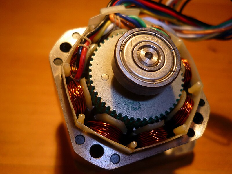
2. Stepper motor :-
A stepper motor is a brushless DC electric motor that divides a full rotation into a number of equal steps. The motor's position can then be commanded to move and hold at one of these steps without any feedback sensor (an open loop controller), as long as the motor is carefully sized to the application. DC brushed motors rotate continuously when voltage is applied to their terminals.
The 3 main types of motors that are commonly used for robotic purposes are :-
 |
| DC geated motor |
 |
| Stepper motor |
The stepper motor is known by its important property to convert a train of input pulses (typically square wave pulses) into a precisely defined increment in the shaft position. Each pulse moves the shaft through a fixed angle. Stepper motors effectively have multiple "toothed" electromagnets arranged around a central gear-shaped piece of iron. The electromagnets are energized by an external control circuit, such as a microcontroller. To make the motor shaft turn, first, one electromagnet is given power, which magnetically attracts the gear's teeth. When the gear's teeth are aligned to the first electromagnet, they are slightly offset from the next electromagnet. So when the next electromagnet is turned on and the first is turned off, the gear rotates slightly to align with the next one, and from there the process is repeated. Each of those rotations is called a "step", with an integer number of steps making a full rotation. In that way, the motor can be turned by a precise angle.
 |
| Servo motor |
3. Servomotor : A servomotor is a rotor actuator that allows for precise control of angular position, velocity and acceleration. It consists of a suitable motor coupled to a sensor for position feedback. It also requires a relatively sophisticated controller, often a dedicated module designed specifically for use with servomotors.
Servomotors are not a specific class of motor although the term servomotor is often used to refer to a motor suitable for use in a closed-loop control system.
In our next post we will be discussing in detail about the microcontrollers , their types and their architectures.
Comments and views will be appreciated.
ReplyDeletethe blog is nice.im really enjoyed the above information.the information is mainly based on studying.
RPA Training in Chennai
Robotics Process Automation Training in Chennai
RPA course in Chennai
Blue Prism Training in Chennai
UiPath Training in Chennai
UiPath Training Institutes in Chennai